Technical Specifications
Transport
Transport
Nauhria precast is an integral part of New Zealand's construction industry, manufacturing and delivering concrete componenets to the commercial, civil and residential construction sectors. the company specialises in concrete precast wall panels, columns, beams, lintels, stairs, balconies and landings. Nauhria also exclusively manufacture and supply the award-winning Monarc Creative Precast Panels.
Get in TouchNZ Standards
Get in Touch
NZ Standards
Reinforcing Steel should be designed by Professional Engineers in accordance with NZ Standards.
Conforming with the standards will ensure that NZ buildings will perform to keep people safe when faced with New Zealand's unique Climate and Seismic events.
NZ Standard requirements to refer when designing Reinforcing Steel should include:
- AS/NZS 4671:2019 - Steel reinforcing MaterialsThe AS/NZS 4671 Standard Sets out for New Zealand Steel reinforcing materials (bars, coils and welded mesh). Requirements for chemical, mechanical and physical properties for three different strength grades and the three different ductility classes are also covered. In New Zealand High Tensile Class 500E grade is primarily used.
- AS/NZS 1554.3:2014 Structural steel welding - Part 3
Part 3: Welding of reinforcing steel provides a code for the welding of reinforcing steel. It specifies requirements for the welding of reinforcing steel used in concrete structures that comply with AS 3600 or NZS 3101.1.Part 3 applies specifically to the welding of reinforcing steels complying with AS/NZS 4671.
NOTE: WELDING OF GRADE 500-E REINFORCING BAR IS ONLY PERMITTED WHERE INSTRUCTED BY THE PROJECT ENGINEER UNDER CONTROLLED CONDITIONS.
- NZS 3101:2006 - Concrete Structures Standard-The design of concrete structures
- NZS 3109:1997 - Concrete construction
Get in Touch
Material Standard
Material Standard
AS/NZS 4671 was introduced in 2001 and is the joint standard for Steel Reinforcement Materials in New Zealand and Australia.
Specific to New Zealand, AS/NZS 4671:2001 (Page 12, Table 2) stipulates.
|
CHARACTERISTIC MECHANICAL PROPERTIES
OF REINFORCING STEELS |
|||
| Property | 300E (Seismic) |
500E (Seismic) |
Type of specified value |
|
Yield stress (Mpa) Rek.L
Rek.U |
> 300 < 380 |
> 500 < 650 |
CvL: p = 0.95 CvU: p = 0.05 |
| Ratio Rm/Re
|
> 1.15 < 1.50 |
> 1.15 < 1.40 |
CvL: p = 0.90 CvU: p = 0.10 |
|
Uniform elongation
Agt(%)
|
> 5.0 |
> 10.0 |
CvL: p = 0.90 |
AS/NZS 4671 allows for the manufacture of material by both the Quench and Tempered (QT) process and the Micro Alloy (MA) process.
Bar Types & Bar Markings


Bar Types / Markings
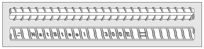
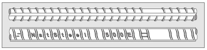
Reinforcing Steel supplied by Nauhria is manufactured by Natseel Singapore and can be clearly identified by Specific markings on the bar in accordance with AS/NZS4671
Instock Product Range:
| Bartype (eg: HD16) | Description | Bar Diameters carried in stock |
| R (eg. R10) | 300E Grade - Round | 6mm, 10mm, 12mm, 16mm, |
| D (eg. D10) | 300E Grade - Deformed | 10mm, 12mm, 16mm, 20mm |
| HR (eg. HR10) | 500E High Tensile (MA) - Round | 10mm, 12mm, 16mm, 20mm |
| HD (eg. HD10) | 500E High Tensile (MA) - Deformed | 10mm, 12mm, 16mm, 20mm |
| RB (eg. RB10) | 500E High Tensile (MA) - Reidbar | 10mm, 12mm, 16mm, 20mm, 25mm, 32mm |
Note:
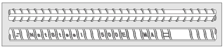
All grade 500E high tensile bars are manufactured using the Micro Alloy (MA) Process.
For specialised applications - Other bar diameters and product may be available, please enquire with us.
Barmarkings
500E grade (MA) Micro Alloy Deformed Bars.
Minimum Bend Radius
Minimum Bend Radius
Incorrect bending can severely affect the performance of steel reinforcement in service. The result can be premature fracture, which will affect the capacity of the building elements to carry design loads. Of particular concern is the practice of bending reinforcing steel to too small a bend diameter.
Bending then straightening (rebending) the reinforcing on site is of even greater concern.
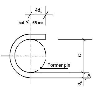
To avoid fracture or weakening, NZS 3109:1997 Concrete construction requires that hooks and bends are formed in accordance with the bend requirements of Table 3.1. The minimum diameter of bend is measured on the inside of the bar.
|
Grade, fy (MPa) |
Bar type |
Bar diameter, db (mm) |
Minimum diameter of bend, di (mm) |
|
|
Plain bars |
Deformed bars |
|||
|
300 or 500 |
Stirrups and ties |
6–20 |
2db |
4db |
|
24 |
3db |
6db |
||
|
All other bars |
6–20 |
5db |
5db |
|
|
24–40 |
6db |
6db |
||
Note that the above table only gives part of the requirements. For full details of standard hooks, bends, stirrups or ties, for mesh bend diameter requirements and for galvanised bar bend requirements, refer to clause 3.3 of NZS 3109:1997.
Rebending should only be carried out when unavoidable and identified at the design stage. NZS 3109:1997 and NZS 3101.1&2:2006 Concrete structures standard require that rebending is done in the specified manner and to the manufacturer’s requirements.
Specific dimensions by component for your convenience.
MAIN BARS | Minimum Bend Radius
MAIN BARS
The minimum bend diameter for main bars, measured to the inside of the bar, shall be equal to or greater than five bar diameters (5db) for 6-20mm and six bar diameters (6db) for 25-32mm.
| Steel Grade |
Bar Diameter - (Round & Deformed) |
Minimum Bend Diameter |
| 300E or 500E
|
6mm | 30mm |
| 10mm | 50mm | |
| 12mm | 60mm | |
| 16mm | 80mm | |
| 20mm | 100mm | |
| 25mm | 150mm | |
| 32mm | 192mm |
STIRRUPS & LINKS | Minimum Bend Radius
STIRRUPS & LINKS
The minimum bend diameter for main diameter for main bars, measured to the inside of the bar, shall be equal to or greater than 2-bar diameters for 6-20mm and 3 bar diameters for 25-32mm for plain bar, and equal to or greater than 4-bar diameters for 6-20mm and 6-bar diameters for 25-32mm for deformed bar.
| Steel Grade |
Bar Diameter |
Minimum Bend Diameter | |
| Round Bar |
Deformed Bar |
||
| 300E or 500E | 6mm | 12mm | 24mm |
| 10mm | 20mm | 40mm | |
| 12mm | 24mm | 48mm | |
| 16mm | 32mm | 64mm | |
| 20mm | 40mm | 80mm | |
| 25mm | 75mm | 150mm | |
| 32mm | 96mm | 192mm | |
If for any reason you believe it is not possible to achieve the minimum bend radius, please seek Engineers' approval before making any adjustments. No adjustments are to be made without engineer approval.
STANDARD HOOKS | Minimum Bend Radius & Hook Length


Standard Hooks
There are three types of standard hooks:
Semi-Circular Hook
A semi-circular turn plus an extension of at least four bar diameters but equal or greater than 65mm at the free end of the bar;
| Bar Diameter | Minimum Semi-circular Hook Length |
| 6mm | 65mm |
| 10mm | 65mm |
| 12mm | 65mm |
| 16mm | 65mm |
| 20mm | 80mm |
| 25mm | 100mm |
| 32mm | 128 mm |
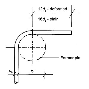
90˚ Hook
A 90˚ turn plus an extension of at least 12 bar diameters at the free end of the bar for a deformed bar and 16 bar diameters for plain bars;
| Bar Diameter | Minimum 90˚ Hook Length | |
| Deformed | Round | |
| 6mm | 72mm | 96mm |
| 10mm | 120mm | 160mm |
| 12mm | 144mm | 192mm |
| 16mm | 192mm | 256mm |
| 20mm | 240mm | 320mm |
| 25mm | 300mm | 400mm |
| 32mm | 384mm | 512mm |
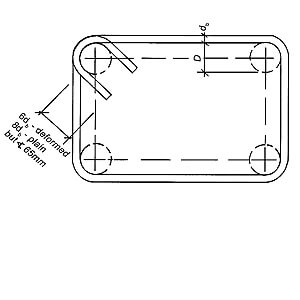
Stirrup Hook
A 135˚ turn around a longitudinal bar plus an extension of at least six stirrup bar diameters for deformed bars and eight stirrup bar diameters for plain bars at the free end of the bar embedded in the core concrete member.
| Bar Diameter | Minimum 90˚ Hook Length | |
| Deformed | Round | |
| 6mm | 72mm | 96mm |
| 10mm | 120mm | 160mm |
| 12mm | 144mm | 192mm |
| 16mm | 192mm | 256mm |
| 20mm | 240mm | 320mm |
| 25mm | 300mm | 400mm |
| 32mm | 384mm | 512mm |
PIle Splices

Pile Splices
NZ 3101 and 3109 require the anchorage of all pile splices/laps to be one of the following:
- A 135˚ hook (as per a stirrup hook)
- A welded lap splice
- A mechanical connector
The above technical data is taken from the Standards 3101 and 3109, full copies are available from Standards New Zealand. Or contact us for further information.
Calculating Rebar Weights


Calculating Rebar Weights
NB: All calculations are external dimensions
Calculating Weights (in kg)
To calculate the weight of a bar: take the length of the bar and multiply it by the factor below corresponding to the bar diameter.
| Bar size | Kg/metre |
| 6mm | 0.222 |
| 10mm | 0.617 |
| 12mm | 0.888 |
| 16mm | 1.578 |
| 20mm | 2.466 |
| 25mm | 3.853 |
| 32mm | 6.313 |
| 40mm | 9.865 |
Stirrups - Calculating the Cut Length
Length of the bar = (2 x A) + (2 x B) + C
C
6mm = 100mm
10mm = 120mm
12mm = 150mm
16mm = 180mm
Links - Calculating the Cut Length
Length of bar = A + C

C
6mm = 150mm
10mm = 200mm
12mm = 250mm
16mm = 300mm
20mm = 360mm
Legs - calculating the Cut Length
Length of bar = A+ B - C
C
6mm = 10mm
10mm = 25mm
12mm = 30mm
16mm = 40mm
20mm = 50mm
25mm = 70mm
32mm = 90mm
Mesh Substitution
Mesh Substitution
In some instances it may be possible to substitute a ductile mesh products with a more cost effective ductile mesh equivalent product.
Substitution mesh can reduce overlaps adding to economic savings to the mesh component of a project.
Substitutions can accomodate variability in bar diameter requiring less bar and larger spacing between bars without comprimising the minimum total steel reinforcing applied to the application.
All substitutions are subject to product availability and engineers approval.
Mesh Conversion Factors:
| Sectional Area | Bars/Meter | Sectional Area/Meter | ||||
|---|---|---|---|---|---|---|
| 668 | 4.00mm | 12.571mm2 | 1000/150 | 6.667 | 12.571 x 6.667 | 83.811mm2 |
| 84 | 5.60mm | 24.640mm2 | 1000/300 | 3.333 | 24.640 x 3.333 | 82.125mm2 |
| 665 | 5.30mm | 22.071mm2 | 1000/150 | 6.667 | 22.071 x 6.667 | 147.147mm2 |
| 147 | 7.50mm | 44.196mm2 | 1000/300 | 3.333 | 44.196 x 3.333 | 147.305mm2 |
| 664 | 6.00mm | 28.286mm2 | 1000/150 | 6.667 | 28.286 x 6.667 | 185.582mm2 |
| 188 | 7.50mm | 44.196mm2 | 1000/235 | 4.255 | 44.196 x 4.255 | 188.054mm2 |
| 663 | 6.30mm | 31.185mm2 | 1000/150 | 6.667 | 31.185 x 6.667 | 207.910mm2 |
| 212 | 9.00mm | 63.643mm2 | 1000/300 | 3.333 | 63.643 x 3.333 | 212.122mm2 |
| 662 | 7.10mm | 39.608mm2 | 1000/150 | 6.667 | 39.608 x 6.667 | 264.067mm2 |
| 265 | 9.00mm | 63.643mm2 | 1000/240 | 4.167 | 63.643 x 4.167 | 265.200mm2 |
| 661 | 7.50mm | 44.196mm2 | 1000/150 | 6.667 | 44.196 x 6.667 | 294.655mm2 |
| 295 | 9.00mm | 63.643mm2 | 1000/215 | 4.651 | 63.643 x 4.651 | 296.004mm2 |
Terms & Conditions - Reinforcing

Terms of Trade
Nauhria Reinforcing Terms & Conditions are provided with all quotations and establish an agreed level of expectations for all parties to agree upon.
The document also provides trade specific consideration and interpretation to generic clauses contained in subcontract agreements for the purpose of providing clarity and avoidance of doubt as to their interpretation.
In the event a subcontract shall become in effect they are to be included as subcontract documents for the address of any clauses not contained nor provided for in the Subcontract documents.
Click Image to download PDF
Nauhria Group Policies
Company Policies - Nauhria Group
Click Thumbnail to view PDF